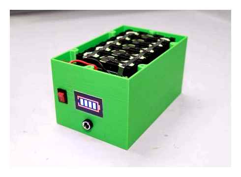
DIY LiFePO4 Battery Review After 400 Days of Continuous Use
It’s been a little over a year since we built and installed our DIY LiFePO4 pack into our Sprinter van. We built a 280Ah LiFePO4 12.8 volt pack using new, grade A prismatic cells I bought from AliExpress. Using a 4S Daly BMS and an active cell balancer, our pack was built at less than half of the price of a comparable commercially made pack. We also added temperature sensors, a cooling fan as well as 12-volt silicone heating pads to make it safe to use in extreme weather conditions. It is designed and built to be much more capable than most off-the-shelf commercially made battery packs. But of course, as a DIY project, there is no warranty against failures so if you plan to build your own, make sure you understand all of the safety measures and assume all of the risks yourself.
How Did We Use It Over This Past Year?
So a lot of people have been asking just how well the pack has held up over regular use. Well, we wanted to wait until we have had at least a year under our belts before sharing our experience. So here it is.
In this past year, we have traveled all across Croatia from Korcula Island to the south all the way up to Zagreb to the north. We left Croatia six months ago and made our way across western Europe through Slovenia, Austria, Germany, and France before taking a ferry to Ireland for the summer months.
In Ireland, we drove along the entire island on the coastal route and explored the world-famous Wild Atlantic Way. We ferried from Belfast to Scotland and drove the North Coast 500 route in the highlands before making our way back to mainland Europe. During that time, we experience plenty of rainy and overcast days which put our battery to the test.
How Our Camper Consumes The Power
Our 280 Ah of LiFePO4 never failed us. We only charged it using our 400 watts of solar on the roof, occasionally supplemented by a 200-watt ground deployed array and our 20A DC-to-DC charger when the engine is running.
We rarely dip below 50% capacity during the entire year. To give you an idea of what we run off of this electrical system so you can predict whether or not this would be enough for you, here is the complete power audit of the van’s electrical system. Your setup will likely be somewhat different but this includes all the appliances and electronic devices that most people will have in their camper vans.
Some of you might wonder so let me tell you that we currently do not use induction cooking powered from ours. We only use it when we have electric hookups. They can draw a huge amount of power and will require about twice our current battery and solar capacity in order to sustain it.
Here is a list of everyone that uses battery power in our van and how much it uses each day:
- A CFX3 75DZ Dometic fridge/freezer. (25 Ah per day)
- 2 Fan-Tastic Fans (0 – 20 Ah per day)
- Several Android and iOS devices (6 – 12 Ah per day)
- 2 laptops (0 – 15 Ah per day)
- 4 led lights (1 Ah per day)
- Webasto diesel heater (0 – 5 Ah per day)
- Propane gas detector (1 Ah per day)
- 12-volt water pump (2 Ah per day)
- Drone charger and camera chargers (0 – 10 Ah per day)
There are other things like a Viair 450P air compressor and Wi-Fi extender that we sometimes use but these are the devices that are more frequently draw power.
Note that out of all of these devices, only the laptops and the drone charger requires the use of our 1,000-watt inverter. We have designed our system to not rely too much on AC power so it is only turned on when needed. This helps to cut down on parasitic draw.
Something I haven’t shared any information about is a DIY home automation system. There are a handful of Smart devices and a Raspberry Pi 4 that is always on as well. The draw is minimal but since I have not talked much about them, I will leave the details for a future post where I plan to share more about how I incorporated home automation technology to some parts of the van and how it has helped out day to day lives.
Our Feedback On The System
So how well has the battery pack been working? the short answer is that it’s been great. It has practically been a seamless and maintenance-free transition from our old 225Ah AGM batteries that we replaced.
The new charging profiles from our solar and DC to DC charger have been doing a great job of keeping the pack topped off. Even during extended days of overcast skies, the extra capacity has kept us from worrying about losing power and as long as we drive every couple of days, we can sustain these less than ideal solar days.
Itemed Needed:
A Bunch of 18650 Cells: (Pick 1)
- Here are some links to purchase bulk cells at HEAVILY reduced (March 2018 Links) LG 2600mAh – ~450.35cell – Some tech labor required to break open plastic shells but its the BEST deal for the capacity: https://www.ebay.com/itm/99-LG-18650-2600MAH-LGABB41865-CELLS-LITHIUM-ION-BATTERIES-POWERWALL-EBIKE-EV/202227213667?hash=item2f15ae6563:g:jbwAAOSwg8taKuC7
- Samsung 2600mAh ~ 450.40 cell – Some tech labor required to break open plastic shells but its a good deal for the capacity: https://www.ebay.com/itm/99-Samsung-18650-2600MAH-ICR18650-26F-CELL-LITHIUM-ION-BATTERIES-POWERWALL-EBIKE/173220714149?hash=item2854c256a5:g:MxkAAOSwnBJarEKz
- Generic 2000mAh ~ 450 cell – Comes already as loose single cells: https://www.ebay.com/itm/50-1801-2000mah-MOLICEL-18650-ICR18650H-CELL-LITHIUM-ION-BATTERY-POWERWALL-DIY/173223651996?hash=item2854ef2a9c:g:RHEAAOSwxnVanZCj
- Pre-Built 20,000mAh 12.6 Lithium Ion Battery Pack of 18650 cells. If you can only solder an XLR cable and not much else, this is the route for you. You could fit 2 of these into a small hard case if you wanted a mega battery: http://amzn.to/2IHB3VM
3S BMS PCB circuit: This will do the all the thinking and processing when it comes time to solder the 18650 cells. You do not need a 3S BMS PCB board if you choose the route of buying a Pre-built 20,000mAh pack.
12.6V Lithium Charger
- http://amzn.to/2FYxMzD – This is no ordinary DC power adapter. It monitors the load to also indicate if its pushing power through or if the BMS circuit has cut it off to protect from over charging the cells. It’s also a 2 phase charger to make sure your cells are charged all the way up to 4.2V each.
Small Pelican Style Case
- I used the Harbor Freight 1800 Watertight Case. It’s a pelican knock off for 14.99 (coupons will reduce it to 9.99) and it works VERY well. I reviewed the case HERE. If you want to buy a real Pelican case go ahead… we will be violating the f out of the lifetime warranty though. https://www.harborfreight.com/1800-watertight-protective-case-9-316-in-63518.html
- If you are looking at the Pelican 1120 for 30 you can see that the Apache 1800 is larger by alot. It’s even a little taller than the Pelican 1200 at 40. The Apache 1800 really is the best deal for a DIY project.
4 Pin XLR – Male and Female (You need all 3 below)
- Female Panel Mount – http://amzn.to/2puzRNi
- Male Panel Mount – http://amzn.to/2FZ2ZCu
- Female Cable Connector (To put a new connector on the charger) http://amzn.to/2Gan0JF
LED Battery Meter (Pick 1)
- Battery Meter that will display how much battery you have left – http://amzn.to/2G8WtwC
- “Luxury Model” voltage display that will also calculate your current amp draw and energy used. but won’t tell you how much of your battery is left unless you memorize your voltage cutoff and cell curves (not for newbs) – http://amzn.to/2psBLxY
- Basic 3S Lithium Battery Display showing remaining capacity. Requires a 3D printer to finish it off with a bevel – http://amzn.to/2u6e7w3S
Standard WavReport Workbench Tools:
- Dremel – http://amzn.to/2ppfQb5
- Basic Soldering Iron Kit – http://amzn.to/2HSJMDb (A nicer kit would be nice, but this is a pretty simple soldering job that doesn’t require alot of fancy soldering gadgets)
- Flush Cutters – http://amzn.to/2IG4B6e (Actually this is my favorite flush cutter on the market. I have 3 that I keep in different tool boxes depending on the task I’m doing.)
- Soldering Helping Hand – http://amzn.to/2DH377W
- Drill – https://www.harborfreight.com/18-volt-38-in-cordless-drilldriver-with-keyless-chuck-21-clutch-settings-62868.html (Yes I know this cordless drill sells for 15 with a coupon at Harbor Freight but we are cutting into plastic using a Titanium drill bit… even a 15 drill will eat plastic all day.)
- Stepping Drill Bit- https://www.harborfreight.com/2-piece-titanium-nitride-coated-high-speed-steel-step-drills-96275.html
STEP 1:
Drill your holes into your case. For Neutrik D Series you will want to drill a whole 24mm or 7/8 Inch.
I used some electrical tape to mark my depth on my stepping drill bit for my second hole because the Switchcraft 4pin XLR is slightly narrower. It only required a 3/4” size hole.
Step 2:
With a black sharpie and a metal ruler draw out where your LED meter will sit. Drill out 4 pilot holes in your corners and use your Dremel to cut out the rectangle. Try your best to cut inside the line, you can always grind the hole open if you need too but you can’t add plastic back. I knew I would be 3D printing labels and a large faceplate. If you do find that you need to open up your hole more you can use the grinding blade on your Dremel or a flat metal file will work also.
Step 4:
UPDATE: If you bought the already built 20,000mAh pack just solder a 2.1 Male DC plug to some wire and follow the wiring steps form P/P-. you can ignore the talk about columns, rows, and B-pads on the BMS board, your 20,000mAh pack already has all that done
Wire Up your 18650s into rows and columns. Here is a block wiring setup. I found it best to have the XLR panel mounts installed in the case when wiring the Battery Meter jumpers to the right pins.
Each “column” of cells is wired to the next and to the next in a series. All the cells in a single column are wired in parallel to each other, this determines the batteries capacity. Each column MUST have the same number of cells, otherwise the battery will default it’s capacity to which ever column has the least amount of cells. The number of “rows” of columns a battery pack has determines how big a battery pack is. The above block wiring setup displays 27x 18650 cells wired in what is called a 3S9P setup. 3S refers to how many cells make up the series, in this case 3. A traditional IDX-NP1 and Inspire Energy/Hi-Q battery is a 4S battery but is only 3P. The 3P in an NP1/Hi-Q battery refers to the fact that those battery packs only have 3x 18650 cells in parallel. To determine the capacity of a battery you take the cells individual capacity and multiply it against the number of cells in parallel. This pelican style battery can be as big or as small as you want, as long as you have room inside the case. If you bought the Apache 1800 case I estimated you could fit 48 cells inside of it for a 4S12P setup. For the battery I built I stuck with a 3S9P setup but opted to use some 3000mAh 18650 cells that I reclaimed from some brand new lithium cordless drill batteries.
Now I know the big block wiring setup can be confusing so I will show you on a smaller setup what you need to worry about when you wire up your battery.
- B- = Zero Voltage. This is the negative terminal where your battery pack starts
- B1 = 3.7v. At this point in your battery chain you are really only messaging “1” group of cells. In this photo that actually means only 1 cell. But if you had 9 cells in parallel they still would only measure out to 3.7v nominal but instead would have a combined capacity.
- B2 = 7.2v. This wire measures the voltage of 2 cells in series. And the IC chip on the BMS board subtract the voltage measured at B1 against B2 to determine this individual groups voltage. This is how the BMS balances out each group of cells against the other groups so that 1 group’s voltage doesn’t dip out of control. The better matched your over all pack’s cells capacity is the more balanced and thus more predictable your pack will behave. Running test and checking each cells capacity before building your pack is called bottom balancing, the idea being when you get to the end voltage on the bottom side of your pack that 95% of your cells are all spent and you don’t have a bunch of cells that are still holding onto juice that can’t be used anymore because you’ve reached the packs overall cutoff voltage. Unlike NiMH and Akline that will continue to putout even a small charge after they are considered “dead” a lithium pack using a BMS will output zero volts because the BMS circuit has a cutoff voltage to protect the cells form dipping below 2.75v per cell and some BMS boards will cut off that voltage even higher.
- B = The same as B2 but it is measuring the last cell in the series. This goes for all BMS boards no matter how many series they allow. You can have BMS boards that go up to 10S and the last one will always be marked as B. B will also have the same voltage as P and on some boards be a substitute for P if the data sheet says so.
- P-/P = This is your main output and neutral/return. The voltage of P is the combined voltage of the series.
Now look at our original diagram again for our pelican style battery pack.
Notice that P goes to Pin 4 on both of the XLR connectors and P- goes to Pin 1 on both of the XLR connectors. This is standard across all film equipment that uses 4 pin XLR for power. For my build I wired the positive terminal of my battery meter to Pin 3 on both of my XLR ports. I researched high and low to determine if Pin 3 is used in any 4pin XLR power ports and if using this pin would cause any conflicts. To the best of my knowledge (and thanks to the guys at Cannibal Industries) only the PSC Power Max uses these pins and the cables that would be plugged into the Power Max won’t cause any conflict with this pelican battery BUT that cables designed to use Pin 3 to trigger the battery meter will cause problems for the Power Max.
What Is the Charging and Current Capability of Power Banks?
The current and charging capacities of power banks are usually different. Previous generation power banks had small capacities of 1000mAh. On the other hand, recent devices come with a huge 25000mAh or more. over, most recent power banks dish out 2.5A currents that allow for fast charging with a portable charger.
All power banks have one thing in common: a rechargeable battery. These rechargeable batteries revolve around lithium technology. Currently, power banks use lithium-ion and lithium-polymer batteries. Lithium-ion batteries can store a lot of electrical charges in a specific volume. Plus, it’s cheaper to manufacture and has a longer lifespan. Modern Lithium-ion Battery On the other hand, lithium-polymer batteries don’t have a long life. Also, it’s more expensive to produce these batteries. Regardless of the battery type, power banks work well. But you need to find the perfect balance between performance and cost.
How Does a Power Bank Work?
As we mentioned earlier, there are different types of power banks. One of them includes a Ni-Cd power bank. This emergency charger pack circuit uses rechargeable 1.2v Ni-Cd cells batteries to dish out 4.8v—by arranging four of these cells. The structure of a Ni-Cd battery Plus, it makes this charger pack circuit the optimal charge of all kinds of mobile phones. However, if you build a 3.7V Li-Ion battery cell power bank, the voltage might not be suitable for charging a cell phone battery with the same voltage parameter. Why? Because connecting two similar batteries would create a situation where the cells exchange power to achieve an equilibrium condition. So, it means that both sides will get an equal amount of charge. Here’s an example: If you fully charge a 3.7V power bank to about 4.2v and then use it to charge a mobile phone with a drained 3.3v cell, both sides would try to reach a level = (3.3 4.2) / 2 = 3.75V by exchanging power. Nickel Cadmium Batteries Nevertheless, we can’t consider 3.75v as the full charge level—as most mobile phones require a full charge level of 4.2v for an optimal charge.
- 18650 Lithium cell
- Slide switch
- 3v to 5v boost converter
- TP4056 Module
Here’s a circuit diagram to help you understand how this power bank works:
Power bank circuit diagram
Source: Wikimedia Commons
The battery is our DIY power bank’s first component. So, we used a 18650 lithium-ion cell (18 mm in diameter and 65mm in height). Plus, these cells come with different capacities and are rechargeable with an output of 3.7v.
Next, we connected our TP4056 module to carry out a constant charger (CC) charging method.
TP4056 Module Structure
Here, the charger applies constant current while increasing the voltage till it reaches the limit.
After that, the TP4056 applies a voltage equal to the maximum cell limit, which slowly reduces to the lower current threshold—with 3% of constant current.

Plus, this module has two LED indicators, which includes:
- The first LED (L1) shines red when the power bank is charging
- The second LED (L2) shines blue when the charging is complete
Furthermore, the battery in the power bank only provides 3.7v, and we needed more than that (up to 5v) to charge a mobile phone.
So, we connected a 3v to 5v boost converter board module, which increased the power bank‘s overall output to 5v. Plus, the module comes with a universal USB female (type-A) port. And it has an indicator that lights up when there’s a current supply from the battery.
Finally, we connected a slide switch to turn on/off the power of the portable charger.
How to Make a Power Bank at Home
Now that you’re familiar with how a power bank works, it’s time to learn how to make one.
So, here are the steps you need to follow:
Step 1: Get Your Materials Ready
Here are the materials you need to build this circuit:
- 18650 Li-ion cells
- Wires
- Protective case
- TP-4056
- Soldering iron
- Step up module
- Solder wire
Step 2: Create Your Battery Pack
Before creating your battery pack, confirm that the voltage for the batteries is the same—especially if you’re using two or more batteries.

After confirming the voltages, use some hot glue or tape to join the batteries. Next, connect the matching battery terminals (anode to anode and cathode to cathode)—with wires. Finally, use your soldering iron to secure the wires.
Step 3: Build Your Circuit
Here, you connect the negative terminal (cathode) of the battery to the.ve terminal of the step-up module and TP-4056. Then, you merge the positive terminals (anodes) to the ve terminal. But that’s not all. You can adjust the step-up module’s output to 5v with a potentiometer. Finally, join the USB port to the step-up module’s output.
Step 4: Test and Fix Problems
You can now charge your mobile device.
This circuit only charges mobile phones that use less than 700mA. But thankfully, you can easily solve this problem by salvaging the PCB of an old power bank, preferably one with a 10,000 mAh capacity. Or, you can use a DC 0.9. 5V, 3V. 5V boost converter module to increase the capacity.
Step 5: Finish Touches
Install a new 5 mm white LED and push button with your soldering iron on the power bank’s PCB. By doing so, you add finishing touches.
Step 6: Cover Up the Circuit
Finally, don’t leave the circuit exposed. Hence, use a protective case to keep your circuit protected. You can use see-through covers or a standard power bank casing.
So, that’s how you make a simple power bank at home.
Parts Tools Required
Some of those are affiliate links. Just trying to recoup the hosting cost!
BOM
My pack is a 3S2P pack with the appropriate BMS ordered from Banggood.

Wire Gauge
Make sure to size your wires appropriately, to prevent unnecessary heat loss or worse, fire hazards. There are many handy calculators online that help you find the right wire gauge for your needs.
Sourcing the battery cells
Purchase Online
You can find various stores online selling 18650 battery cells in bulk. You can pick and choose the ones that fit your requirements and order them online. Beware of scams though, as it’s not uncommon for shady sellers to sell counterfeit battery cells. These usually have far lower ratings than advertised, and could cause catastrophic failure if brought beyond their limits.
Scavenging
Then there is the alternative of scavenging 18650 battery cells that you might already have lying around. Chances are that you do! A common source of these cells are laptop battery packs and battery packs meant for power tools. It’s likely that even failed battery packs still have plenty of reusable cells inside. Check out my article on how to harvest Lithium-Ion cells from old batteries!
Personally this appeals to the maker in me, and also allows to extend the use of battery cells that still have plenty of life left and aren’t ripe for the dump yet. However, it doesn’t come without its own drawbacks. Removing the cells can be tricky, and you could damage the cells (and yourself) if you’re not careful.
Assembly
Insert Cells
First you need to arrange the battery brackets in a fashion that allows you to solder the nickel strip to the positive and negative terminals as required.
Inserting/Arranging cells
In the gallery I re-used scavenged batteries that have some remains of nickel strips still attached.
Solder/Weld the connections
Important! Make sure the cells have a similar charge before connecting them in parallel. Otherwise, there will be a high current flow between the batteries, which could result in damage or even fire. Ideally the cells should be between 3.5 – 3.7 V.
Unless you’re regularly building your own battery packs, chances are you don’t have a spot-welder on hand. Well, neither do I. Soldering the nickel strips to the terminals is frowned upon, because it exposes the cells to large amounts of heat, causing degradation.
Well, you have to work with the tools you got. Soldering the nickel strips isn’t pretty, but it gets the job done. If you use batteries that already have tabs attached, you can try soldering the nickel strips to those instead. This reduces the heat the cells are exposed to.
If you correctly inserted the battery cells into the frames, it should now be clear how to solder them together. Take the nickel strip and solder them appropriate to your cell arrangement. Make sure to leave a few extra cm of the nickel strip on the side where you want to attach your BMS.
Add the BMS
Time to add the BMS! Chances are the BMS is already designed to be used in a battery pack. Check the wiring diagram of your BMS and attach it to your battery pack. I used some hot-glue to stick it in place.
Wire the BMS
Attach the nickel strips and connect them to the nickel strips on the battery terminals as shown in your BMS wiring diagram. In the image below is an example based on the BMS used for my 3S2P battery pack.
Attach two wires which will be your battery leads to the P and P- terminals. Make sure the wire gauge is rated for the maximum current you expect your battery to handle. I suggest also using XT wire terminals, to make attaching the battery to your projects easier. The number after the XT letters stands for the maximum current they’re rated for.
Wrap the batteries
For the finishing touch, you might want to wrap your battery pack. I used wire insulation tape to create a makeshift wrap. In hindsight, I don’t recommend it, because the adhesive seems to degrade over time. Ideally you’d want heat shrink wrap, but I found the ones with the necessary size too expensive for my taste. It might be worth experimenting with other wrapping techniques to protect the cells and BMS from damage.
Charge
Time to charge the battery pack! I used my bench power supply and configured it with the appropriate maximum charging current and voltage settings. These depend on the cells used in your battery pack, as well as the BMS used. Check the specification sheets of both to make sure which settings to use!
Conclusion
If everything worked out as expected, you should now have a complete and charged battery pack, ready to be used in a project of your choice! The steps described above should work for most other battery configurations.
If this is more than a one-off for you, it might be worth checking into getting a battery spot-welder. There are various options out there, from 20€ Chinesium boards to several thousand € professional machines. An open-source, DIY alternative is the kWeld spot-welder from keenlabs.